 Work Experience
A quick glance at my professional experience
Senior Staff Software Engineer
2025 - Present
- Lead System Level Test manufacturing development for PCIe cards, multi-card hosts, UBB trays & server racks
- Architected & implemented HAL based Python SLT framework scalable across all products (card to server)
- Automated SLT release, validation and monitoring pipelines across factory floors in North America and Taiwan
- Deployed & supported mfg suite; debug line-stop issues across PCIe, Ethernet, thermal, FW, HW, and tooling
- Reduced SLT runtime from 120 to 70 mins & improved system yield by ~30% compared to legacy framework
- Built structured logging, error taxonomy, & a factory dashboard for yield, runtimes, and recurring failure trends
Staff Software Engineer
2024 - 2025
- Analyze & scoped SOC features to develop test plans for AMD data center products (MI300X family)
- Architected HW abstraction libs & tests referencing the ASIC architecture and specification docs in C++ & python
- Engineered high stress, di/dt inducing apps to define ASIC V-F curve & bounding box for AMD HPC ASICs
- Led horizontal team of 10+ engineers driving daily standups, load balance, triage JIRA tasks & reviewing commits
Senior Software Engineer
2021 - 2024
Software Engineer II
2019 - 2021
Contract Software Engineer
2024 - 2024
- Led a team of 6 interns to develop automated test execution framework for Meta data center products in python
- Independently contributed over 3,000 lines of significant code to repository within the first 3 months on the team
- Drove daily stand-ups, managed technical debt, reviewed commits and assigned sprint tasks to engineers
- Curated weekly team output & regression reports to present to managers & technical leads
Development Engineering Intern
2017 - 2018
- Developed server-rack testers for embedded systems & PCBs in A&D, consumer & health tech industry
- Automated data acquisition and tester flow in LABVIEW using NI & Keysight equipment
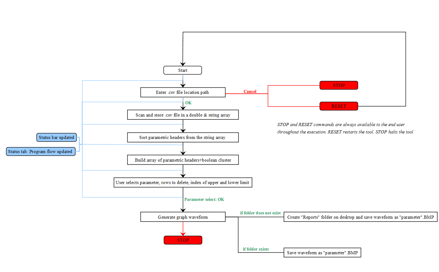
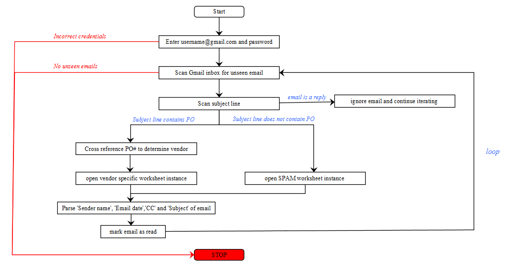
- Automated purchases and data entries using Python by extracting data from emails & google sheets
 Skills
Technical and management skills overview
Languages
- C++, bash(shell), HTML+CSS, Javascript, Python, MySQL, XML
Technologies
- Cmake, Confluence, GDB, Git, JIRA, Linux, Visual Studio, NodeJS, React
Hardware
- ASICs, DMMs, EEPROMS, FPGA emulation, Microcontrollers, Oscilloscopes, System on Chips
Subjects
- ASIC validation, GPU kernel development, Hardware abstraction/driver development,HPC/GPU architecture, Pre-silicon validation, System Level Test development
Management
- Project management, Team leadership, Cross-functional collaboration, Resource allocation, Risk management, Agile methodologies, Stakeholder management
 Achievements
History of academic and professional recognition
- 2026 TT Cash Bonus: In recognition of implementing the new SLT, improving yield and reducing run-time
- 2025 AMD spotlight award for discovering RTL bug and workaround on MI355X predictive droop detection feature
- 2025 AMD spotlight award for developing and achieving the Most Stressful Application title for MI350X
- 2023 AMD spotlight award for developing and achieving the Most Stressful Application title for MI300X
- 2023 AMD spotlight award for excellent execution across MI300 BTO, BU and drive to production milestones
- 2022 AMD spotlight award for leading team of 9 developers through MI300's marathon 7-day bringup
- 2020 AMD Spotlight Award for successfully completing pre-silicon verification ahead of deadline
- 2019 Achieved a position in the dean's list for my academic performance in 4th year
- 2019 Earned the bronze medal for final year capstone project in Electrical Engineering at Ryerson University
- 2018 Achieved second position ($100.00) in ex Battle of Ideas (Ryerson) out of 38 competitors
- 2018 Awarded Bravo! (Celestica performance award) for delivering on aggressive timelines and project management skills
 Education
Overview of my post-secondary education
Bachelor of Engineering (B.Eng)
September 2014 - May 2019
Through my B.Eng at TMU (formerly Ryerson University), I gained in-depth theoretical knowledge on a variety of topics. This, coupled with hands-on, practical experience of working in laboratories has enabled me to contribute towards the success of my employers and personal projects. The focus of specialization was Embedded Systems and Systems on Chips.
Relevant Courses (IIIrd & IVth year)
Control systems, Microprocessors, Power Electronics, Software systems, CMOS mixed mode analysis, Computer networks, Computer organization and architecture, Electronic Circuits I/II, Embedded system design, Low power digital IC, Operating Systems, Realtime computer control systems, SOC design.
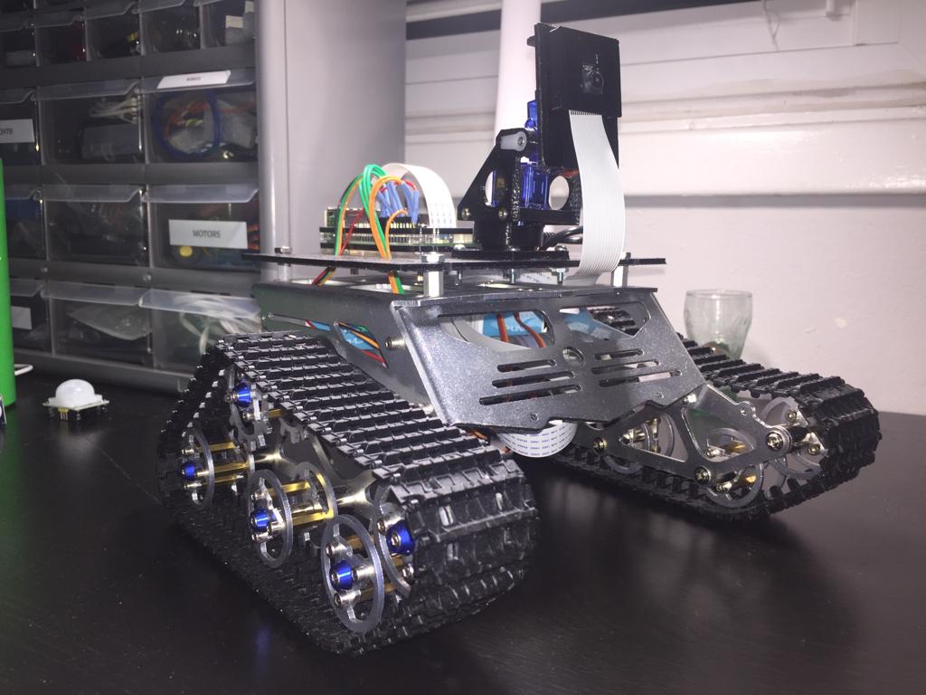
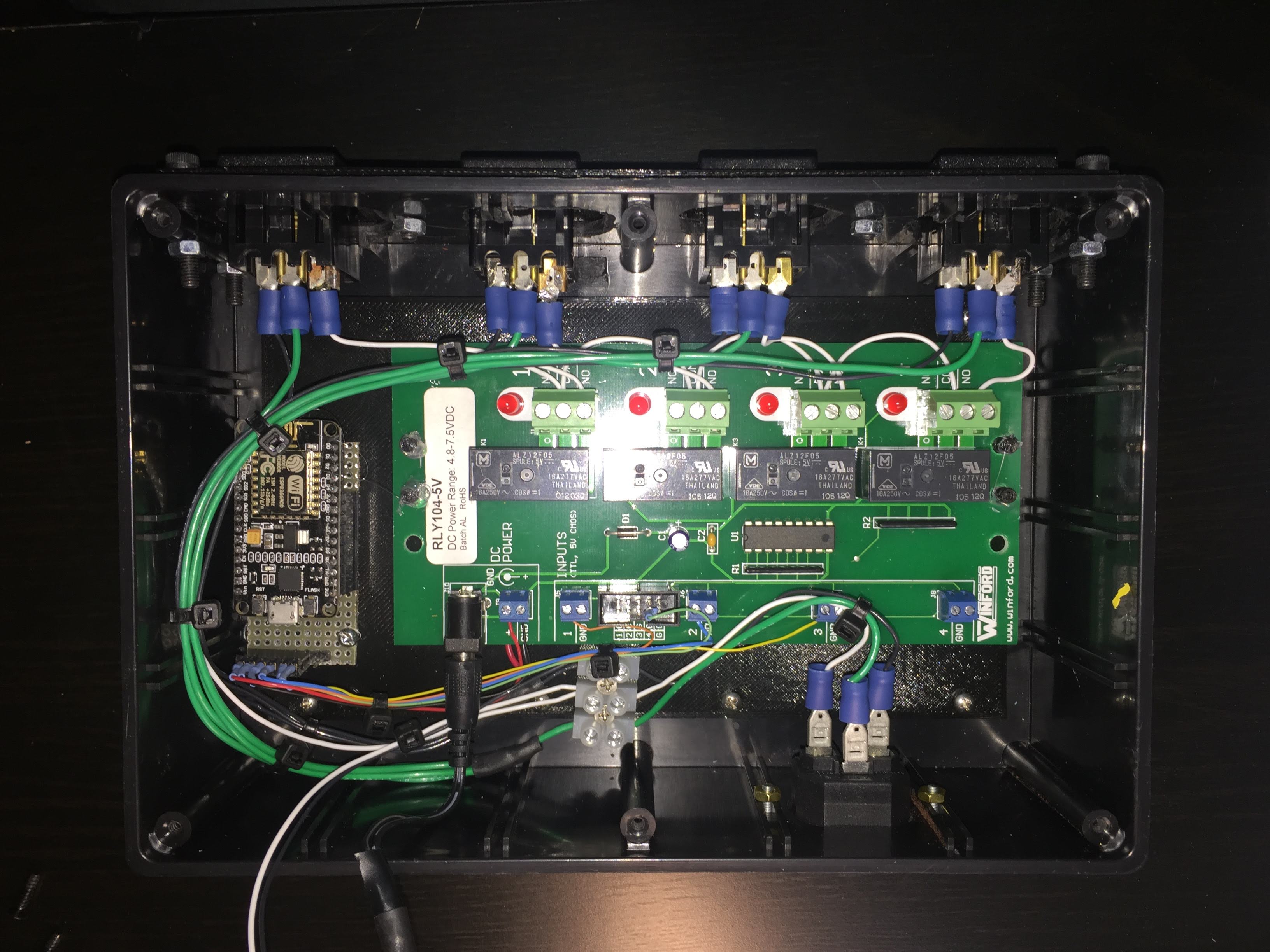
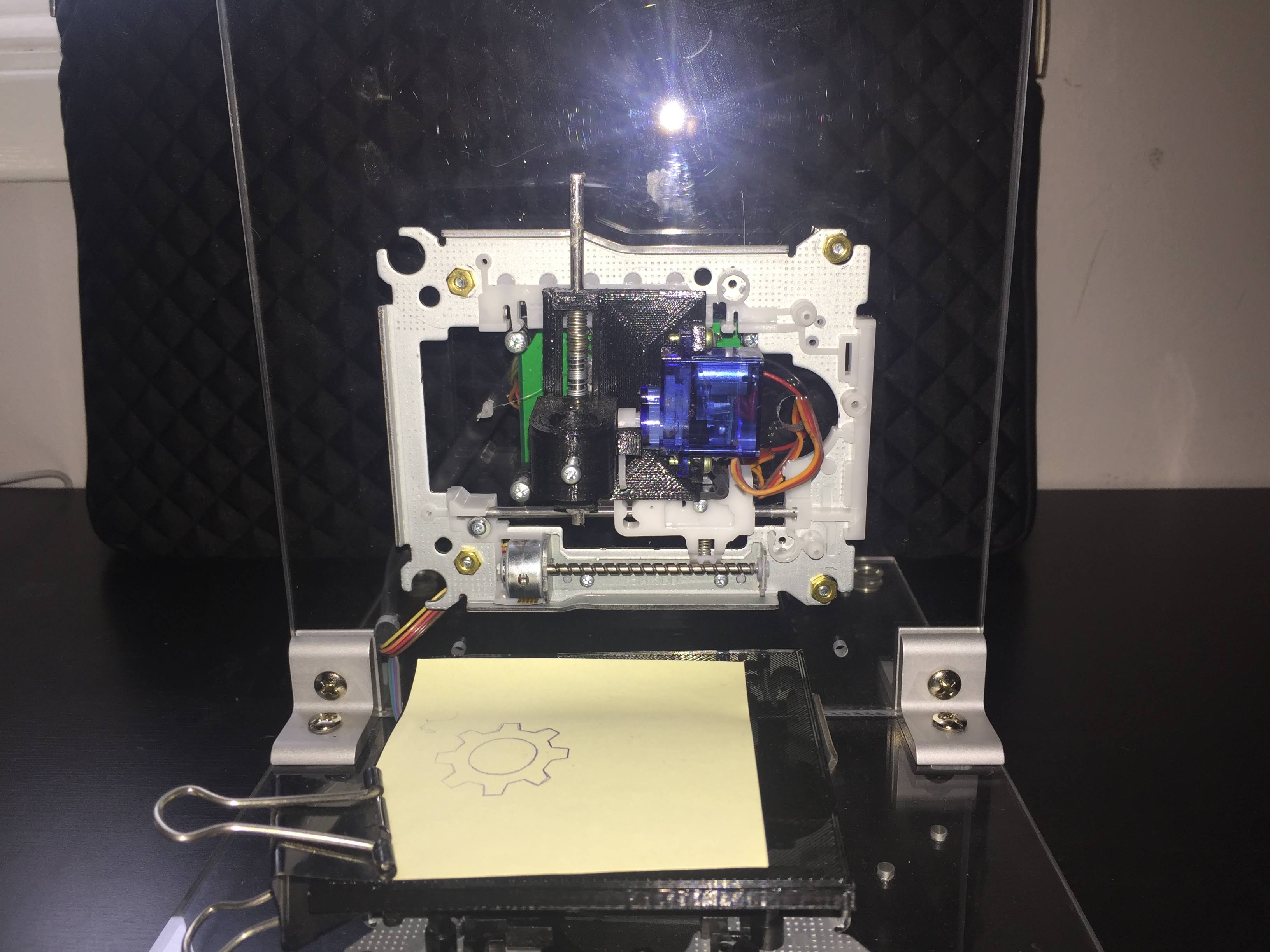
 Projects
 Contact Me
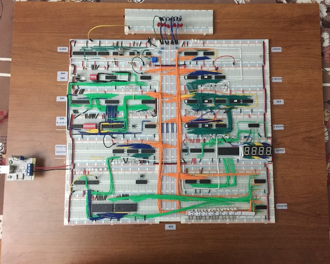