SECOND ORDER PLL
Second order Phase Locked Loop consisting of 4 stages
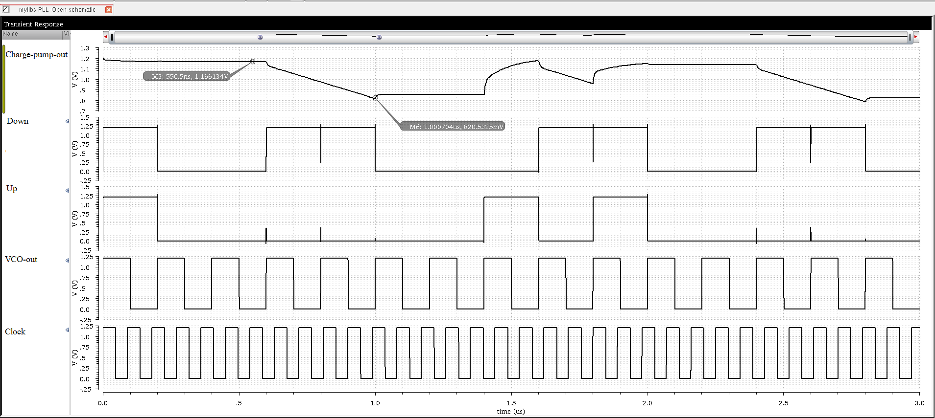
Project Overview
Phase locked loops are widely used to synchronize and synthesize frequencies in microelctronics. The above image is the open-loop response of a 10 MHz PLL designed as per the requirements of laboratory 2 for ELE 724 (CMOS Mixed-Mode Circuits) using TSMC 130nm technology in Cadence. A typical second order, 4 stage PLL consists of (1) Voltage Controlled Oscillator (2) Phase-Frequency Detector (3) Charge Pump and a (4) Loop Filter. The PFD detects the phase difference in between the reference voltage and sends an UP/DOWN signal to the CP accordingly. The CP, depending on the output of PFD, either sources or sinks the Control Voltage of the VCO which in turn decreases or increases the frequency of VCO output. Therefore, a PLL locks on to the phase of the input, not the frequency!
Key Points
- If UP = DOWN, Control Voltage = NC, VCO output frequency = NC
- UP > DOWN, Control Votlage increases, VCO output frequency decreases
- UP < DOWN, Control Votlage decreases, VCO output frequency increases